1. Rules for the design of architectural and construction drawings (according to GOST 21.501-93): implementation of the building plan.
General information.
The main and working drawings are carried out in line drawing, using lines of different thicknesses, due to which the necessary expressiveness of the image is achieved. In this case, the elements that fall into the cut are highlighted with a thicker line, and the visible areas behind the section are thinner. The smallest thickness of lines made in pencil is approximately 0.3 mm, in ink - 0.2 mm, the maximum line thickness is 1.5 mm. The thickness of the line is selected depending on the scale of the drawing and its content - plan, facade, section or detail.
Scales images in the drawings should be selected from the following row: to reduce -1:2; 1:5; 1:10; 1:20; 1:25; 1:50; 1:100; 1:200; 1:400; 1:500; 1:800; 1:1000; 1:2000; 1:5000; 1:10,000; to increase - 2:1; 10:1; 20:1; 50:1; 100:1.
The choice of scale depends on the content of the drawing (plans, facades, sections, details) and the size of the object depicted in the drawing. Plans, facades, sections of small buildings are usually made on a scale of 1:50; drawings of large buildings are performed on a smaller scale - 1:100 or 1:200; very large industrial buildings sometimes require a scale of 1:400 - 1:500. Units and details of any buildings are performed on a scale of 1:2 - 1:25.
Coordination axes, dimension and extension lines. Coordination axes determine the position of the structural elements of the building, the dimensions of steps and spans. Axial lines are applied with a dash-dotted thin line with long strokes and are marked with marks that are put down in circles.
On the plans of buildings, the longitudinal axes, as a rule, are taken out to the left of the drawing, the transverse ones - from the bottom. If the location of the axes of the opposite sides of the plan does not match, then their markings are placed on all sides of the plan. In this case, the numbering is done through. The transverse axes are marked with ordinal Arabic numerals from left to right, and the longitudinal ones are marked with capital letters of the Russian alphabet (except for E, Z, Y, O, X, Y, E) upwards.
The diameter of the circles must correspond to the scale of the drawing: 6 mm - for 1:400 or less; 8 mm - for 1:200-1:100; 10 mm - for 1:50; 12 mm - for 1:25; 1:20; 1:10..
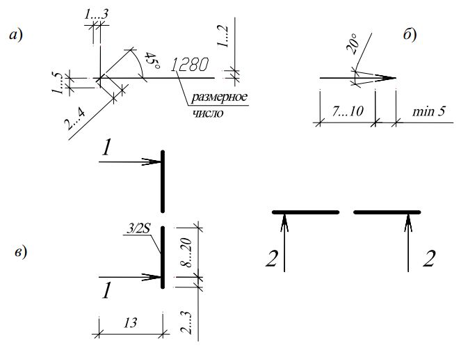
The font size for designating the axes should be 1.5-2 times larger than the font size of the dimensional numbers used in the drawing. Marking of axes on sections, facades, nodes and details must comply with the plan. To apply dimensions on the drawing, dimension and extension lines are drawn. Dimension lines (external) are drawn outside the contour of the drawing in an amount of two to four in accordance with the nature of the object and the design stage. On the first line from the drawing indicate the dimensions of the smallest divisions, on the next - larger ones. On the last dimension line, the total size between the extreme axes is indicated with the binding of these axes to the outer faces of the walls. Dimension lines should be applied so that it is not difficult to read the drawing itself. Based on this, the first line is drawn at a distance from the drawing no closer than 15-21 mm. The distance between the dimension lines is taken at 6-8 mm. The segments on the dimension lines corresponding to the dimensions of the outer elements of the walls (windows, partition, etc.) are limited by extension lines, which should be applied starting at a small distance (3-4 mm) from the drawing, to the intersection with the dimension line. The intersections are fixed with serifs having a slope of 45 °. With very closely spaced small sizes in the drawings of parts and assemblies, serifs are allowed to be replaced by dots. Dimension lines should protrude beyond the extreme extension lines by 1-3 mm.
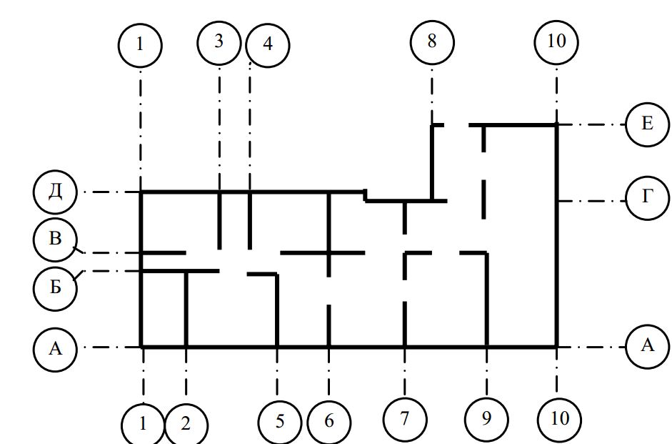
On the internal dimension lines indicate the linear dimensions of the premises, the thickness of the partitions and internal walls, width of door openings, etc. These lines should be drawn at a sufficient distance from the inner edges of walls or partitions so as not to obstruct the reading of the drawing.  Rules drawings plans in accordance with the requirements of ESKD and SPDS (schematic drawing): a - coordination axes; b - dimension lines; in-wire lines; g - area of premises; e - cut lines (dimensions are given in millimeters).
Dimensional and extension lines are drawn with a thin solid line. All dimensions are given in millimeters without a dimension designation. The numbers are applied above the dimension line parallel to it and, if possible, closer to the middle of the segment. The height of the numbers is selected depending on the scale of the drawing and must be at least 2.5 mm when done in ink and 3.5 mm when done in pencil. ^
Level marks and slopes. Marks determine the position of architectural and structural elements on sections and facades, and on plans - in the presence of differences in floor levels. The level marks are counted from the conditional zero mark, which, as a rule, is taken for buildings as the level of the finished floor or the upper edge of the floor of the first floor. Marks below zero are indicated with a "-" sign, marks above zero - without a sign. The numerical value of the marks is put down in meters with three decimal places without indicating the dimension. 
Rules for applying marks, sizes and other designations on sections in accordance with the requirements of ESKD and SPDS (schematic drawing). To indicate the mark on facades, sections and sections, a symbol is used in the form of an arrow with sides inclined to the horizontal at an angle of 45 °, based on the contour line of the element (for example, the edge of the finished floor or ceiling plane) or on the extension line of the element level (for example, the top or the bottom of a window opening, horizontal ledges, exterior walls). In this case, the marks of the external elements are taken out of the drawing, and the internal ones are placed inside the drawing 
On the plans, marks are applied in a rectangle or on a leader line shelf with a “+” or “-” sign. On architectural plans, marks are usually placed in a rectangle, on structural drawings to indicate the bottom of channels, pits, various openings in the floors - on the leader line. 
The magnitude of the slope on the sections should be indicated as a simple or decimal fraction (up to the third digit) and denoted by a special sign, the acute angle of which is directed towards the slope. This designation is applied above the contour line or on the shelf of the leader line 

On the plans, the direction of the slope of the planes should be indicated by an arrow indicating the magnitude of the slope above it.
Designation of cuts and sections show an open line (trace of the beginning and end of the cutting plane), which is taken out of the image. With a complex broken cut, traces of the intersection of cutting planes are shown
At a distance of 2-3 mm from the ends of the open line extended beyond the drawing, arrows are drawn that indicate the direction of view. Sections and sections are marked with numbers or letters of the Russian alphabet, which are placed under the arrows in transverse sections and on the side of the outer side of the arrows - in longitudinal ones. See the illustration on the right for the arrows' style and size. ^
Designation of the areas of premises. Areas expressed in square meters with two decimal places without a dimension designation, they are usually put down in the lower right corner of the plan of each room. The numbers are underlined. In the drawings of projects of residential buildings, in addition, the residential and useful (total) area of \u200b\u200beach apartment is marked, which is indicated by a fraction, the numerator of which indicates residential apartment area, in the denominator - useful. The fraction is preceded by a number indicating the number of rooms in the apartment. This designation is placed on the plan of a large room or, if the area of \u200b\u200bthe drawing allows, on the plan of the front. ^
Remote inscriptions, explaining the names of individual parts of structures in nodes, are placed on a broken leader line, the inclined section of which with a dot or arrow at the end faces the part, and the horizontal one serves as a shelf - the basis for the inscription. With a small scale of the drawing, the leader line can be completed without an arrow and a dot. Remote inscriptions to multilayer structures are applied in the form of so-called "flags". The sequence of inscriptions relating to individual layers must correspond to the order of the layers in the structure from top to bottom or from left to right. The thickness of the layers is indicated in millimeters without dimension. Marks of structural elements on the layout diagrams are applied on the shelves of leader lines. It is allowed to combine several leader lines with a common shelf or put a mark without a leader next to the image of the elements or within the contour. The font size for designating brands should be larger than the font size numbers on the same drawing 
Marking nodes and fragments - important element design drawings to help them read. The main purpose of marking is to link nodes and fragments taken out on a larger scale with detailed areas on the main drawing.
When placing nodes, the corresponding place on the facade, plan or section is marked with a closed solid line (circle or oval) with an indication on the shelf of the leader line with a number or letter of the serial number of the element to be taken out. If the node is located on another sheet, then under the shelf of the leader line, indicate the number of the sheet on which the node is placed 
Above the image or on the side of the rendered node (regardless of which sheet it is placed on), a double circle is placed with the designation of the serial number of the node. Circle diameter 10-14 mm
Technical construction drawings are accompanied by the names of individual images, textual explanations, tables of specifications, etc. For these purposes, a standard roman font with a letter height of 2.5 is used; 3.5; 7; 10; 14 mm. In this case, the font height is 5; 7; 10 mm is used for the names of the graphic part of the drawing; 2.5 and 3.5 mm high - for text material (notes, stamp filling, etc.), 10 and 14 mm high - mainly for illustrative drawings. Image titles are placed above the drawings. These names and headings of text explanations are underlined line by line with a solid line. Headings of specifications and other tables are placed above them, but not underlined.
^ Floor plan.
In the names of plans in the drawings, it is necessary to follow the accepted terminology; architectural plans should indicate the mark of the finished floor or the floor number, for example, “Plan for elev. 0.000", "Plan of 3-16 floors", it is allowed to indicate the purpose of the premises of the floor in the names of the plans, for example, "Plan of the technical underground", "Plan of the attic"
Floor plan depicted as a section by a horizontal plane passing at the level of window and door openings (slightly above the window sill) or 1/3 of the height of the depicted floor. With a multi-tiered arrangement of windows on one floor, the plan is depicted within the window openings of the lower tier. All structural elements that fall into the section (steles, pillars, columns) are outlined with a thickened line
On floor plans apply:
1) coordination axes of the building with a dash-dotted thin line;
2) chains of external and internal dimensions, including the distances between the coordination axes, the thickness of walls, partitions, the dimensions of window and door openings (in this case, internal dimensions are applied inside the drawing, external - outside);
3) marks of the levels of clean floors (only if the floors are located at different levels);
4) cut lines (cut lines are carried out, as a rule, in such a way that the openings of windows, external gates and doors fall into the cut);
5) marking of window and door openings, lintels (it is allowed to mark the openings of gates and doors in circles with a diameter of 5 mm);
5) designations of nodes and fragments of plans;
6) names of premises, their area
The names of the premises are allowed, their areas are given in the explications in form 2. In this case, instead of the names of the premises, their numbers are put down on the plans.
Form 2
Explication of premises

Built-in premises and other sections of the building, on which separate drawings are made, are schematically depicted as a solid thin line showing load-bearing structures.
Platforms, mezzanines and other structures located above the cutting plane are depicted schematically by a dash-dotted thin line with two points
^
An example of a floor plan for a residential building:
Floor plan elements.
Lightweight concrete block walls. ^
Symbol in plan: The wall thickness is a multiple of 100mm. The thickness of the inner (bearing) wall is min 200 mm. The thickness of the outer walls is 500, 600 mm + 50, 100 mm of insulation. The dimensions of the standard block are 390x190x190mm. ^
The walls are brick. The wall thickness is a multiple of 130mm (130, 250, 380, 510, 640mm). The thickness of the inner (bearing) wall is 250, 380 mm. The thickness of the outer walls is 510, 640 mm + 50, 100 mm of insulation. The dimensions of an ordinary ceramic brick are 250x120x65 (88) mm. ^
Timber walls. Wall thickness (150) 180, 220 mm. The thickness of the inner (bearing) wall is min 180 mm. The thickness of the outer walls is 180, 220 mm. ^
The walls are timbered. Wall thickness 180, 200, 220 - 320 mm (multiple of 20mm). The thickness of the inner (bearing) wall is min 180 mm. The thickness of the outer walls is 180 - 320 mm. ^
Walls - a wooden framework with filling from an effective heater. The thickness of the frame stand is 100, 150, 180mm + 40-50mm double-sided plating. The thickness of the inner (bearing) wall is 100 + 40-50 mm. The thickness of the outer walls is 150, 180 + 40-50 mm. Partitions:


from lightweight concrete blocks, thickness 190mm;

brick, thickness 120mm;

three-layer wooden, thickness 75mm;

plasterboard metal frame, thickness 50-70mm.
Window openings:

v brick walls Oh;

in timber, log and frame walls.
Doorways external:
in walls made of lightweight concrete blocks;

brick walls;

and frame walls. Doorways internal:

for all types of walls.
GOST 21.101-97
INTERSTATE STANDARD
SYSTEM OF DESIGN DOCUMENTS FOR CONSTRUCTION
MAIN REQUIREMENTS FOR PROJECT AND WORKING DOCUMENTATION
5. GENERAL RULES FOR DOCUMENTATION
Coordination axes
5.4. Coordination axes are indicated on the image of each building or structure and assigned to them independent system designations.
Coordination axes are applied to the images of the building, structures with thin dash-dotted lines with long strokes, denoted by Arabic numerals and capital letters of the Russian alphabet (with the exception of the letters: Ё, 3, Ъ, O, X, C, Ch, Щ, b, Y, b) in circles with a diameter of 6-12 mm.
Gaps in digital and alphabetic (other than indicated) designations coordination axes not allowed.
5.5.
The numbers indicate the coordination axes along the side of the building and structures with a large number of axes. If there are not enough letters of the alphabet to designate the coordination axes, subsequent axes are designated by two letters.
Example: AA; BB; VV.
5.6. The sequence of numerical and alphabetic designations of the coordination axes is taken according to the plan from left to right and from bottom to top (Fig. 1a) or as shown in Fig. 1b, c.
5.7.
The designation of the coordination axes, as a rule, is applied on the left and lower sides of the plan of the building and structure.
If the coordination axes of the opposite sides of the plan do not coincide, the designations of these axes at the divergence points are additionally applied on the upper and / or right sides.
5.8.
For individual elements located between the coordination axes of the main supporting structures, additional axes are applied and denoted as a fraction:
above the line indicate the designation of the previous coordination axis;
under the line - additional serial number within the area between adjacent coordination axes in accordance with fig. 1g
It is allowed to assign numerical and alphabetic designations to the coordinating axes of half-timbered columns in continuation of the designations of the axes of the main columns without an additional number.
5.9. On the image of a repeating element attached to several coordination axes, the coordination axes are designated in accordance with Fig. 2:
"a" - with the number of coordination axes not more than 3;
"b" - with more than 3 coordination axes;
"c" - for all alphabetic and digital coordination axes.
If necessary, the orientation of the coordination axis, to which the element is attached, in relation to the neighboring axis, is indicated in accordance with Fig. 2y.

Rice. 2
5.10.
To designate the coordination axes of block sections of residential buildings, the index "c" is used.
Examples: 1s, 2s, Ac, Bs.
On the plans of residential buildings, arranged from block sections, the designations of the extreme coordination axes of the block sections are indicated without an index in accordance with Fig. 3.

Rice. 3
Building floor plans
Working drawings of architectural solutions
Building floor plan- this is an image of a section of a building made by an imaginary horizontal cutting plane passing at the level of window and door openings or at a height of 1/3 of the height of the depicted floor of the building.
The floor plan gives an idea of the configuration and dimensions of the building, reveals the shape and location of individual rooms, window and door openings, main walls, columns, stairs, partitions. The contours of the building elements (walls, piers, pillars, partitions, etc.) that fall into the cut and are located behind the cutting plane are applied to the plan.
If the floor plans of a multi-storey building have slight differences from each other, then the plan of one of the floors is completely fulfilled, for other floors, only the parts of the plan necessary to show the difference from the plan depicted in full are performed.
Coordination (layout) axes- these are coordination lines that determine the division of a building or structure into modular steps and floor heights. They determine the position of the main load-bearing structures of the building and pass along its main walls and columns.
These axes, which can be longitudinal or transverse, divide the building into a number of elements.
On the images of each building and structure, coordination axes are indicated, which are assigned an independent notation system. Coordination axes are applied with dash-dotted lines with long strokes in accordance with Figure 5. On the plans, the center axes are taken out of the contour of the walls and are indicated in capital letters of the Russian alphabet and Arabic numerals (numbers), which are recorded in marking circles with a diameter of 6-12 mm. The marking circles of the coordination axes are placed at a distance of 4 mm from the last dimension line.
For marking on the side of a building with a large number of axes, numbers are used, and with a smaller number of axes, letters are used, with the exception of the letters E, Z, Y, O, X, C, H, SH, b, Y, b. Letters mark, as a rule, the axis running along the building.
The sequence of numerical and alphabetic designations of the coordination axes is taken according to the plan from left to right and from bottom to top, placing marking circles on the left and bottom sides of the building (Fig. 12, 20).
The designation of the coordination axes, as a rule, is applied on the left and lower sides of the plan of the building and structure. If the coordination axes of the opposite sides of the plan do not match, the designations of the indicated axes are additionally applied at the locations on the upper and / or right sides. Omissions of letters and numbers when marking axes are not allowed.
For individual elements located between the coordination axes of the main supporting structures, additional axes are applied and denoted as a fraction, in the numerator of which the designation of the previous coordination axis is indicated, and in the denominator - an additional serial number within the area between the coordination axes (Fig. 11a).
The construction of the main elements of buildings is carried out using modular size coordination in construction (MKRS), according to which the dimensions of the main space-planning elements of the building must be a multiple of the module.
The main module is taken equal to 100 mm.
The main structural elements (bearing walls, columns) of the building are located along the modular coordination axes(longitudinal and transverse). The distance between the coordination axes in low-rise buildings is taken as a multiple of the 3M module (300 mm).
To determine the relative position of building elements, grid of coordination axes.
Coordination axes are drawn with dash-dotted thin lines and are usually indicated on the left and bottom sides of the plan, marked, starting from the lower left corner, with Arabic numerals (from left to right) and capital letters of the Russian alphabet (from bottom to top) in circles with a diameter of 6 ... 12 mm (Fig. .2).
Rice. 2. An example of marking the coordination axes
Dimensions on construction drawings they are affixed in millimeters and are applied, as a rule, in the form of a closed chain.
Dimension lines are limited to serifs - short strokes 2 ... 4 mm long, drawn with an inclination to the right at an angle of 45 ° to the dimension line. Dimension lines should protrude beyond the extreme extension lines by 1 ... 3 mm. The dimension number is located above the dimension line at a distance of 1 ... 2 mm (Fig. 3, a).
To designate cutting plane positions section or section of a building, an open line is used in the form of separate thickened strokes with arrows indicating the direction of view. The cut line is marked with Arabic numerals (Fig. 3, c). The start and end strokes must not cross the outline of the image.
The dimensions of buildings in height (height of floors) are assigned as multiples of the modules. Floor height of a building is defined as the distance from the floor level of a given floor to the floor level of an overlying floor. In projects of residential buildings, the floor height is assumed to be 2.8; 3.0; 3.3 m
On facades and sections, high-rise marks the level of an element or structure of a building from any calculated level taken as zero. Most often, the level of the finished floor (floor covering) of the first floor is taken as the zero level (mark ± 0.000).
Level marks are indicated in meters with three decimal places without indicating units of length and are placed on extension lines in the form of an arrow with a shelf. The sides of the right angle of the arrow are drawn by a solid thick main line at an angle of 45 ° to the extension line (Fig. 4).
Rice. 3. Inscription of the dimensions and position of the cuts:
a - dimensions and dimension lines; b – gaze direction arrow;
c - positions of cuts

Rice. 4. Drawing level marks on the views:
a - dimensions of the level mark; b - examples of location and design
level marks on cuts and sections; c – the same, with explanatory inscriptions;
d - an example of the image of the level sign on the plans
The mark mark may be accompanied by explanatory inscriptions: Ur.ch.p. - the level of the clean floor; Ur.z. - ground level.
Marks on the plans are applied in rectangles (Fig. 4, d). Marks above the zero level are indicated with a plus sign (for example, + 2.700), below zero - with a minus sign (for example, - 0.200).
The following are accepted in construction drawings: denominations types of buildings.
V names of plans the building indicates the mark of the finished floor of the floor, the floor number or the designation of the corresponding plane; when executing a part of the plan - the axes that limit this part, for example:
Elevation plan +3,000;
2nd floor plan;
Plan 3–3;
Elevation plan 0.000 in axes 21–39, A–D.
V name of cuts of the building, the designation of the corresponding secant plane is indicated (in Arabic numerals), for example, Section 1–1.
V names of facades of the building, the extreme axes are indicated, between which the facade is located, for example:
Facade 1–5;
Facade 12–1;
Facade A-G.
For multilayer structures, portable inscriptions located on shelves in a straight line,
ending with an arrow (Fig. 5). The sequence of inscriptions (material or construction of layers with indication of their thickness) to individual layers must correspond to the sequence of their location on the drawing from top to bottom and from left to right.
On the leader lines, ending with a shelf, additional explanations to the drawing or item numbers of elements in the specification are placed.

Rice. 5. Examples of execution of portable inscriptions
Graphic symbols materials in sections and sections of buildings and structures are given in App. 3. The distance between parallel hatching lines is selected within 1 ... 10 mm, depending on the hatching area and image scale. Material designations are not used in the drawings if the material is homogeneous, if the dimensions of the image do not allow the symbol to be applied.
Conditional graphic images of building elements and sanitary devices are given in App. 4.
Structural size call the design size l building structure, product, element, element of equipment, determined in accordance with the rules of the MKRS (modular coordination of dimensions in construction). Structural dimensions (Fig. 109) take less coordination dimensions l 0 by a gap size of d or more coordination dimensions (with the addition of the value of the protrusions located in the adjacent coordination space). The size of the gap d is set in accordance with the features of the structural units, the operating conditions of the joints, installation and tolerances.
Nominal dimensions l 0 structural elements are the design dimensions of building products and equipment, including standardized clearances d; the normalized gap is the thickness of the seam of the gap between the structural elements established by the norms.
Structural dimensions l- design dimensions of structural elements, building products and equipment.
Rice. 109. Location building structures, products and elements in the coordination space
Natural dimensions structural elements - these are their actual dimensions, which differ from the structural ones by the amount of tolerances established by the standards.
Features of dimensioning on construction drawings. on construction drawings, dimensions are applied in accordance with GOST 2.307-68, taking into account the requirements of the design documentation system for the construction of GOST 21.501-93.
To determine the dimensions of the depicted product (structural element, assembly, building, structure) and its parts, the dimensional numbers printed on the drawing are used. Dimension and extension lines are drawn as a solid thin line with a thickness of S/3 to S/2 (see Fig. 109).
Dimensions in millimeters on construction drawings, as a rule, are applied in the form of a closed chain without indicating the unit of measurement. If the dimensions are given in other units, this is specified in the notes to the drawings. Dimension lines on construction drawings are limited by serifs - short strokes 2-4 mm long, drawn with an inclination to the right at an angle of 45 ° to the dimension line. The thickness of the serif line is equal to the thickness of the solid main line adopted in this drawing. Dimension lines should protrude beyond the extreme extension lines by 1-3 mm. The dimension number is placed above the dimension line at a distance of approximately 0.5 to 1 mm (Fig. 110a, 110b). The extension line should protrude beyond the dimension line by 1-5 mm. With a lack of space for serifs on dimension lines, which are a closed chain, serifs can be replaced with dots (Fig. 110c).

Rice. 110. Limiting dimension lines
The distance from the drawing outline to the first dimension line is recommended to be at least 10 mm. However, in the practice of design work, this distance is taken equal to 14-21 mm. The distance between parallel dimension lines must be at least 7 mm, and from the dimension line to the circle of the coordination axis - 4 mm (Fig. 111).

Rice. 111. An example of applying dimensions to an image with a gap
with one dimension line
If there are a number of identical elements in the image located at equal distances from each other (for example, the axes of columns), the dimensions between them are put down only at the beginning and at the end of the row (Fig. 112) and indicate the total size between the extreme elements as the product of the number of repetitions by repeating size.
The dimension line on construction drawings is limited by arrows in accordance with GOST 2.307-68 if it is required to indicate the diameter, radius of the circle or angle, as well as when applying dimensions from a common base located on a common dimension line (Fig. 113b and Fig. 114)
Rice. 112. An example of applying dimensions to an image with a gap
with multiple dimension lines


Rice. 114. Dimension line
6.6. Building plan
Plan- this is an image of a section of a building, dissected by an imaginary horizontal plane passing at a certain level, as shown in Fig. 115.
According to GOST 21.501–93, this plane should be located at 1/3 of the height of the depicted floor. For residential and public buildings, the imaginary cutting plane is located within the door and window openings of the floor.

A building plan drawing shows what is in the cutting plane and what is below it. Thus, the plan of the building is its horizontal section.
The building plan gives an idea of the shape of the building in plan and the relative position of the individual rooms. The building plan shows window and door openings, the location of partitions and main walls, built-in wardrobes, sanitary Technical equipment etc. Plumbing fixtures are drawn on the building plan on the same scale as the building plan.
If the plan, facade and section of the building are placed on one sheet, then the plan is placed under the facade in projection connection with it. However, due to the large size of the images, plans are usually placed on separate sheets, with their long side located along the sheet.
When starting to draw a plan, it should be remembered that the side of the plan corresponding to the main facade of the building should be turned to the bottom edge of the sheet. When determining a place on a sheet for a drawing of a building plan, the applied dimensions and marking of the coordination axes should be taken into account. Therefore, the plan drawing should be located approximately at a distance of 75 - 80 mm from the sheet frame. In specific cases, these dimensions may vary. After determining the location of the plan on the sheet and its scale, they begin to draw.
1. Draw with a dash-dotted line 0.3 ... 0.4 mm thick the coordination axes of the plan, longitudinal and transverse, as shown in fig. 116. These axes are used to link the building to the construction coordinate grid, as well as to determine the position of load-bearing structures, since these axes are carried out only along the main walls and columns.
The Arabic numerals 1, 2, 3, etc. are used to mark the axes on the side of a building with a large number of them. Most often, a greater number of axes run across the building. To mark the axes on the side of the building with a smaller number, they use the letters of the Russian alphabet A, B, C, etc. Letters mark, as a rule, the axis running along the building. When marking axes, it is not recommended to use the letters: Z, Y, O, X, C, H, SH, Y, b, b. Axes are marked from left to right and from bottom to top. Omissions in the serial numbering and alphabet when designating the coordination axes are not allowed. Usually marking circles (their diameter is 6 ... .12 mm) are located on the left and lower side of the building. Removing the marking circle from the last dimension line 4 mm (see fig. 112)

2. Taking into account the binding of the axes along the MKRS and the thickness of the walls, the contours of the longitudinal and transverse outer and inner walls are drawn with thin lines (Fig. 117).

The main walls are tied to the coordination axes, i.e. determine the distances from the inner and outer plane of the wall to the coordination axis of the building, and the axis can not be drawn along the entire length of the wall, but only by the amount necessary to set the dimensions of the binding. Coordination axes do not always have to coincide with the geometric axes of the walls. Their position should be set taking into account the coordination dimensions used by the standard span structures of beams, trusses or floor slabs. In buildings with load-bearing longitudinal and transverse walls, the binding is performed in accordance with the following guidelines.
In external load-bearing walls, the coordination axis passes from the inner plane of the walls at a distance equal to half the nominal thickness of the internal load-bearing wall, a multiple of the module or its half. In brick walls, this distance is most often taken equal to 200 mm, or equal to the module, i.e. 100 mm (Fig. 118a). In external self-supporting walls, if the floor panels do not go into it, for the convenience of calculating the number of standard floor elements, the coordination axis is combined with the inner face of the wall, which is called zero binding (Fig. 118b). If the floor elements are based on outer wall throughout its thickness, the coordination axis is aligned with the outer face of the wall (Fig. 118c). In the inner walls, the geometric axis of symmetry coincides with the coordination axis (Fig. 118d). Deviation from this rule is allowed for the walls of staircases and walls with ventilation ducts.

Draw the contours of the partitions with two thin lines (Fig. 117). Partitions are tied to marking axes depending on the layout of the premises in the building.
It is necessary to pay attention to the difference in the connection of external and internal main walls and main walls and partitions. If the material of the connected walls is the same, then the walls are drawn as a single unit. If the material of the walls is different, then they are drawn as different elements.
3. At this stage, flights of stairs are depicted and window and door openings are broken down (Fig. 119).

When drawing flights of stairs, the gap between flights should be selected within 100–200 mm, and the width of the treads should be 300 mm.
The symbol for window and door openings with and without filling is shown in accordance with GOST 21.501–93. When drawing a plan on a scale of 1:50 or 1:100, if there are quarters in the openings, their conditional image is given in the drawing. It should be borne in mind that the dimensions of the openings are indicated in GOST without taking into account quarters, therefore, in the drawings, the dimensions are affixed minus quarters, i.e. subtract 130mm from the size of the opening.
It should be remembered that when drawing a partition that limits the vestibule of the entrance, it must be applied after drawing tape marches. This is due to the fact that the dimensions of the vestibule are limited by the dimensions of the interfloor area. The width of the doorway in this partition is similar to the width of the entrance opening, excluding the quarter (see Fig. 119, 122).
Quarter - this is a protrusion in the upper and side parts of the openings of brick walls, which reduces airflow and facilitates the fastening of boxes (Fig. 120). On fig. 120a shows window openings with and without a quarter, and Figure 120b shows doorways with and without a quarter.
It should be noted that when depicting windows on plans and sections on a scale of M1:100 and M1:50, glazing in window openings with a quarter, the first string of glazing is shown in a quarter, and the second is 1 mm inside the building from the first.

The width of the doors is selected from the range: 700 mm for bathroom and toilet; 800 mm or 900 mm for rooms and kitchens; 900 mm or 1000 mm - entrance doors to the apartment; 1200 mm or 1500 mm (two-leaf) - entrance doors to the entrance. When placing a doorway in the wall for interior doors, one should proceed from the convenience of using the premises, the intended arrangement of furniture, etc., which should be taken into account when determining the direction of door opening.
Some recommendations for the placement of doors: the doors to the living rooms and the kitchen should open inwards; doors leading to the bathroom and toilet open outwards; doors should clutter up the room as little as possible.
On the plans door leafs depicted as a solid thin line and open at an angle of approximately 30º (the angle is not indicated in the drawing). Entrance doors The building only opens to the outside.
4. After depicting windows and doors, they show the location of plumbing equipment (Fig. 119): in the kitchen - a sink and stove, in the toilet - a toilet, in the bathroom - a bath and a washbasin. Conditional graphic images of sanitary equipment are performed in accordance with GOST 2.786-70 * and GOST 21.205-93, the dimensions of the most common sanitary equipment are given in fig. 121.

5. Outline the contours of partitions and main walls with lines of appropriate thickness, put down the dimensions and areas of the premises, as shown in fig. 122. When choosing the thickness of the stroke lines, it should be taken into account that non-load-bearing structures, in particular the contours of partitions, are outlined with lines of smaller thickness than the load-bearing main walls.
Dimensions outside the building plan. The first dimension line (chain) with alternating dimensions of walls and openings is drawn at a distance of 15 ... .20 mm from the outer contour of the plan.
On the second dimensional chain indicate the distance between adjacent coordination axes.
On the third dimensional chain indicate the distance between the extreme coordination axes.
The distance between parallel dimension lines (chains) must be at least 7 mm, and from the dimension line to the marking circle of the coordination axis - 4 mm. Circles for designating coordination axes are taken with a diameter of 6 ... .12 mm.
The dimensions of the binding of the outer walls to the coordination axes are put down before the first dimensional chain.
Horizontal traces of imaginary cutting planes of the section are also applied on the plans, on which images of the sections of the building are then built. These traces are thick open strokes 1 mm thick with arrows as shown in Fig. 122. If necessary, the imaginary plane of the cut can be depicted with a thickened dash-dotted line. The direction of the arrows, i.e. direction of view, it is recommended to take from the bottom up or from right to left. However, if necessary, you can choose another direction. Depending on the position of the dimensional chains and the workload of the drawing, they can be placed at the outline of the plan or behind the extreme dimensional chain, as shown in Fig. 122. The secant planes of the cuts are indicated by the letters of the Russian alphabet or numbers.

Dimensions placed inside the building plan. The internal dimensions of the premises (rooms), the thickness of the partitions, internal walls, the dimensions of the doorways are put down on the internal dimension lines (chains). Internal dimension lines are drawn at a distance of at least 8 ... 10 mm from the wall or partition.
Indicate the width and length of the staircase, coordination dimensions the width of the platforms, the length of the horizontal projection of the marches.
The figure of the size of the area with an accuracy of 0.01 m2 is put on the plan in a free place, closer to the lower right corner of each room, underlining it with a solid main line.
Put down the height of the floor and interfloor platforms, and for the first floor - the entrance platform, in a rectangle with an accuracy of the third significant figure after the decimal point, indicating the sign "+" or "-".
An inscription is made above the plan drawing. For industrial buildings, this will be an indication of the floor level of the production facility or site according to the “Plan for elev. +2,500". The word "mark" is abbreviated. For civil buildings in the inscription, you can write the name of the floor according to the type "Plan of the 1st floor". The inscriptions are not underlined.
The plan indicates the name of the premises. If the size of the image does not allow making an inscription on the drawing, then the rooms are numbered, their name is given in the explication. Marking numbers are placed in circles with a diameter of 6 - 8 mm.
Drawings of floor plans are accompanied by an explication of the premises; lists of interior decoration, etc. The shapes and sizes of explications and statements are shown in fig. 123.

● contours of load-bearing walls that fall into the section 0.6 - 0.7mm;
● contours of partitions 0.3 - 0.4mm;
● contours of elements that did not fall into the cut, the image of stairs, plumbing equipment 0.3mm;
● thickness of extension, dimension, center lines, marking circles and other auxiliary lines 0.2mm.
6.7. Control questions
1. What drawings are called construction?
2. List the types of buildings according to their purpose.
3. What is the brand of the main set of working drawings of architectural solutions.
4. What is called a structural element?
5. List the main structural elements of the building.
6. What is a module? What are the meanings of enlarged modules.
7. How are the coordination axes?
8. Features of drawing dimensions on construction drawings.
8. What is called a floor plan?
9. What scale of construction drawings is used to draw plans for residential buildings?
10. How is the plan marked?
11. What is the sequence of the floor plan?
12. How are the mills attached to the marking axes?
13. What is the conditional image in terms of a window opening with a quarter and without quarters?
14. What is the conditional image in terms of a doorway with a quarter and without quarters?
15. How are the elements of sanitary equipment depicted on the plans?
16. What dimensions are applied on the floor plan?
17. How are the areas of premises indicated on the plans?
18. How and what lines are used when tracing the floor plan.
19. What line thickness is used when building a plan
Lecture 7. SECTION
7.1. Level marks of structural elements.
7.2. General information about sections of buildings.
7.3. Methodology for constructing a vertical section of a building.
7.4. Building overlays.
7.5. Construction of window and door openings.
7.5. Control questions.
7.1. Level marks of structural elements
Marks. Conditional level marks (heights, depths) on plans, sections, facades show the distance in height from the surface level of any building structural element located near the planning surface of the earth. This level is taken as zero.
Marks of height levels, depths of structural elements from the reference level (conditional "zero" mark) are indicated in meters with three decimal places separated from the integer by a comma. On facades, sections and sections, marks are placed on the extension lines of the contour.
The conditional "zero" mark is indicated, indicated without the sign " 0,000 ' or with a sign "±0.000" (it is recommended to designate with the sign "±"); marks above zero - with a "+" sign; below zero - with a "-" sign.
On views (facades), sections and sections, marks are placed on extension lines or contour lines and are indicated by a conventional sign. The mark mark is (GOST 21.105 - 79) an arrow with a shelf. In this case, the arrow is made with main lines 2-4 mm long, drawn at an angle of 45 ° to the extension line or contour line. The leader line, vertical or horizontal, is outlined with a solid thin line (Fig. 124a, 124b).

If necessary, the height and length of the shelf can be increased. If several level signs are located one above the other near one image, it is recommended to place the vertical lines of the mark on one vertical straight line, and make the length of the horizontal shelf the same (Fig. 124c).
The mark mark may be accompanied by explanatory inscriptions. For instance: " Lv.p.p." - the level of the clean floor; " Ur.z." - ground level (Fig. 124d).
On construction drawings, level marks in sections (Fig. 125a), facades (Fig. 125b) and plans (Fig. 125c) are indicated in meters with three decimal places separated from the integer by a comma.

The conditional zero mark is indicated as follows: 0.000. A dimensional number showing the level of an element located below the zero mark has a minus sign (for example -1.200), and one located above has a plus sign (for example +2.700).
On the plans, the dimensional number of the marks is applied in a rectangle, the outline of which is circled with a thin solid line, or on the shelf of the leader line. In this case, a plus or minus sign is also placed before the dimension number (Fig. 125c).
7.2. General information about building sections
cut called the image of a building, mentally dissected by a vertical plane, fig. 126. If the plane is perpendicular to the longitudinal axes, then the cut is called cross, and parallel to them longitudinal. Sections in construction drawings serve to identify the volumetric and constructive solution buildings, the relative position of individual structures, premises, etc.
Sections are architectural and constructive.
architectural cuts serve to identify the internal appearance of the premises and the location of the architectural elements of the interior, which do not show the structures of floors, rafters, foundations and other elements, but put down the height of the premises, window and door openings, plinth, etc. The heights of these elements are most often determined by elevations. Architectural sections are made at the initial design stage to work out the facade of the building. For the construction of the building, the architectural section is not used, since it does not show the structural elements of the building, fig. 127.
Structural cuts are carried out at the stage of development of working drawings of the building, which show the structural elements of the building (foundations, rafters, ceilings), and also apply the necessary dimensions and marks, fig. 128.


In working drawings, the direction of view for cuts is taken, as a rule, according to the plan - from bottom to top and from right to left. Sometimes, if necessary, or for educational purposes, the direction of gaze is taken from left to right.
The position of the cutting plane is chosen so that it passes through the most structurally or architecturally important parts of the building: window and doorways, stairwells, balconies, etc. It should be borne in mind that the cut plane along the stairs is always carried out along the marches closest to the observer. In this case, the march of the stairs that has fallen into the cut is outlined with a line of greater thickness (solid main) than the march contour along which the cutting plane does not pass. The contour of this march is outlined with a solid thin line.
