The main elements of an autonomous pumping station are a pump, a storage tank, a pressure switch for a hydraulic accumulator and a check valve. The pressure unit pumps a given volume of water into the network. The hydraulic accumulator accumulates and maintains constant pressure to supply water to the consumer. The control unit ensures a stable operating cycle of the cold water supply system equipment. Let's take a closer look at where it is used and how to configure the hydraulic accumulator and pressure switch.
The water pressure switch regulates the switching on and off of the device supplying water to the hydraulic tank
Hydraulic accumulator in a cold water supply system
Direct connection of a submersible or surface pump causes unstable water supply. The pressure unit runs idle with minimal water consumption. The presence of a gravitational or pneumatic accumulator in the system does not require constant operation of the primary pressure blower. The reserve tank maintains a constant flow of water for household and drinking needs. The water supply reduces the dependence of individual water supply on external factors.
The gravity design of the hydraulic accumulator is an atmospheric tank with a float level sensor. An open tank is installed in the attic of the house, above the water intake points. The pressure in the system creates the weight of the liquid column. The operation of the pump is controlled by a float mechanism or level sensors.

Pumping station with hydraulic accumulator and pressure switch
Modern hydraulic accumulators for autonomous water supply operate due to excess pressure in the air chamber. The operating principle of pneumatic accumulators is based on the interaction of compressed air and water. The pump pumps water into a rubber bulb located inside the housing. The volume of the air chamber decreases and the pressure increases. In the intervals between turning on the unit, air pushes the water supply from the membrane into the consumer network.
Water does not come into contact with the inner walls of the sealed container. An air chamber separates the membrane from the metal housing. If the accumulator is used in a drinking water supply system, then the membrane material is chemically neutral rubber. When using a battery tank in a heating or hot water supply system, membranes with high resistance to high temperatures are used.
![]()
Membrane tank design
There are vertical and horizontal models of pneumatic storage tanks of various capacities. The connection diagram of the hydraulic accumulator is determined by the type of pump and the model of the storage tank. Horizontal tanks are used for remote surface units. The pressure blower is installed on the platform in the upper part of the storage tank body (i.e. the cylinder is located below the self-priming pump).

The pumping station will help to achieve a complete autonomous water supply to the dacha
Calculation of accumulator volume
The method for selecting a hydraulic accumulator is intended for individual houses that consume a large amount of water (sewage, bathroom, shower, several faucets, bidet, washing machine and dishwasher). Based on the number of water withdrawal points, the total consumption coefficient and the maximum water consumption for household and drinking needs are determined. The volume of the accumulator is determined by the formula:
V is the volume of the hydraulic accumulator, l;
Qmax - maximum water consumption for household and drinking needs, l/min;
a is the number of system starts per hour (recommended value 10 starts);
Pmin - pump activation pressure, atm;
Рmax - pump switch-off pressure, atm;
Po - pressure of the air chamber of the hydraulic accumulator, atm.
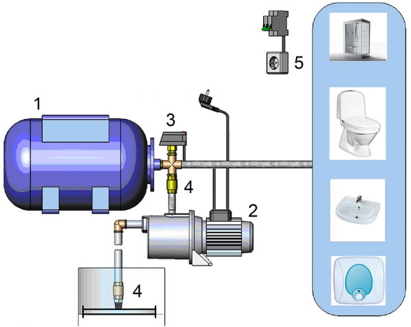
The water supply design consists of: 1 - hydraulic accumulator; 2 - pump; 3 - pressure switch; 4 check valves; 5 - power supply
A standard water supply installation for a small house with seasonal residence is usually equipped with a hydraulic accumulator with a capacity of 24 liters. For a house with more than three collection points, choose a 50-liter storage tank. Moreover, in the technical data sheet of the equipment, the manufacturer indicates the total volume of the cylinder (including the air chamber).
Adjusting the working pressure of the hydraulic accumulator
For domestic water supply of one-story houses, a pressure of one atmosphere is considered sufficient. However, it should be taken into account that the air pressure of the air chamber must exceed the static pressure of the highest point of water extraction.
The maximum shut-off pressure value depends on the pressure characteristics of the pump. The pressure that the pump pumps, divided by 10, corresponds to the value of the upper response threshold for the automatic water supply system. Corrections are made for linear hydraulic resistance, the actual voltage of the electrical network, the technical condition of the equipment and the height of the house’s water supply system.

Accessories for adjusting water pressure in the hydraulic tank
The recommended difference between the pump on and off pressure for autonomous water supply is 1.0÷1.5 atmospheres. Increasing the factory setting (1.5 atmospheres) will reduce the reserve volume and increase the pressure in the system. High pressure of cold water supply increases consumption and leads to irrational use of energy resources.
Formula for calculating the required pressure in the accumulator:
Hmax is the height in meters from the center line of the accumulator to the top point of water extraction (for a two-story private house 6÷7 meters).
The air pressure in the air chamber of the damper tank is checked and adjusted before installation, if the settings fail or the water supply operating mode is disrupted. During adjustment, the power to the pumping station is disconnected from the network, and the water from the accumulator is drained.
![]()
All elements are fastened together using fittings
The pneumatic air chamber valve is located under the decorative cap on the tank body. The correspondence or deviation of pressure from the specified operating parameters is determined using a pressure gauge connected to the spool. Based on the measurement results, excess air is released or the pressure of the air chamber is pumped up with a car pump.
If adjusting the operating parameters of the hydraulic accumulator does not bring the desired result, then check the settings of the pressure switch.
Pressure switch device for hydraulic accumulator
The pressure switch controls the operation of the pump and regulates the filling of the pneumohydraulic accumulator. The device integrates, controls and regulates the operation of cold water supply system equipment.
The appearance of the pump control unit resembles a small plastic box. The device is mounted at the entrance to the storage tank. The pressure switch for the hydraulic accumulator consists of a mechanical and electrical part.
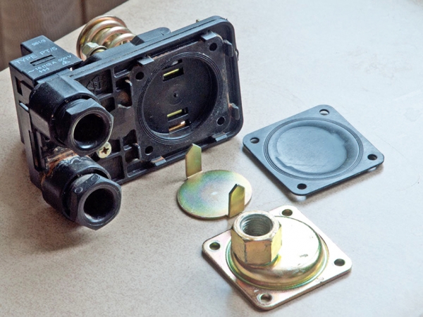
Pressure switch disassembled
Elements of a standard pressure switch design:
- plastic case (cover with screws and base);
- metal membrane cover (with a nut for connection to the pipeline);
- rubber membrane;
- brass piston;
- two studs with threads and nuts;
- large and small adjustment springs;
- metal base plate;
- articulated platform;
- electrical contact unit with flat spring;
- cable clamps;
- terminal block.

Pressure switch design and adjustment
The spring adjustment mechanism and the connection box are protected by a plastic cover. The metal base plate is supported from below by a plastic housing. The base separates the working element (membrane with piston) from the actuator (hinge platform, two adjusting springs on studs and an electrical contact unit).
The electrical part of the water pressure switch is a two-contact switching relay for electrical circuits. The legs of the electrical contact assembly are sandwiched between a metal base plate and a plastic housing. Two couplings for clamping the cable (from the mains and the power supply line to the pump) and the connection point for the relay to the hydraulic accumulator are located on the base of the plastic case.
The standard diameter of the inlet pipe is ¼ inch. On the device side, the internal cross-section of the nut fastening to the adapter is limited by a rubber membrane. The reciprocating movement of the elastic membrane is communicated to a brass piston, which transmits force to a hinged metal platform.

Pressure gauge is used to measure water pressure
From above, on the movable edge of the platform, a large and small spring presses, which counteract the force of the piston. The degree of compression of the large spring regulates the moment the pump turns on. The deformation range of the small spring ensures that the pressure unit is turned off.
Methods for connecting a pressure switch to a hydraulic accumulator
There are different diagrams for connecting a pressure switch to a hydraulic accumulator for water and electricity.
How to connect a water pressure switch?
The connecting pipe of the unit connecting the hydraulic accumulator pressure switch to the pipeline is rigidly fixed. The device is installed in assembled condition. Before starting assembly, it is necessary to ensure sufficient space for rotation of the housing when installing the pressure switch.
The device is screwed onto a thread separately cut into the pipeline or installed directly on the outlet pipe of the hydraulic accumulator through a special fitting. A fitting with five outlets allows you to install a control pressure gauge next to the pump control device.

Connecting wires to the pressure switch
How to connect a pressure switch to a hydraulic accumulator electrically?
Direct connection of the pressure switch is carried out from a 220V network, provided that the operating current of the pump does not exceed 10 Amperes.
Before connecting the cable, remove the protective plastic cover from the device. The electrical cable of the power line or pump is inserted into the appropriate coupling. The wire is secured from the outside with a nut with a plastic crimp ring. The designation of contact groups is indicated on the housing. The end of the cable is divided into cores. The phase, neutral, and grounding are stripped of the insulating braid and connected to the terminals of the contact group.
Important! Electrical installation and adjustment work is carried out with the equipment disconnected from the network. The electrical connection is carried out in compliance with the regulatory rules for technical operation and safety precautions in electrical installations.

The relay automates the operation of the pumping station and turns off the water supply when a set point is reached
Rules for adjusting the pressure switch for a hydraulic accumulator
The relay controls the minimum and maximum pressure in the storage tank and maintains the pressure difference when the pump is turned on/off. The limit of permissible relay setting values depends on the hourly flow rate and pump power.
The characteristics of the factory settings are indicated in the technical data sheet of the product. The standard pressure switch setting value for water supply systems is 1.0÷5.0 atmospheres. Starting pressure - 1.5 atmospheres. The operating range of the pump motor is 2.5 atmospheres. The maximum shutdown pressure of the unit is 5.0 atmospheres.
If the factory settings are not relevant or the installation malfunctions, then the water pressure switch is configured and adjusted independently, using a pressure gauge. The control and measuring device is installed on the accumulator manifold. The correction is made according to the pressure gauge readings after the pump is turned off. The pressure difference is created by opening the tap at the water intake point closest to the accumulator.

Connecting a pressure switch and automation unit to a submersible pump
The hydraulic accumulator pressure switch is adjusted under pressure, without disconnecting the pumping station from the power supply. The pump must fill the storage tank and increase the pressure in the network. When the relay operates and turns off the unit’s engine, it is necessary to remove the plastic housing cover and completely loosen the tension level of the small spring mechanism.
How to adjust the water pressure switch to the minimum pump activation pressure?
Adjusting the large adjustment spring:
- the clamping nut is rotated clockwise to increase the starting pressure;
- weakening the tension - reduces the pressure at which the relay operates and the engine starts;
- To check the result of the adjustment, open the water tap and drain the water until the pump turns on.

The pressure switch is adjusted using two nuts: large and small
How to adjust the accumulator pressure switch according to the pump shut-off pressure?
Setting the small adjustment spring:
- the nut on the small spring stud is tightened to increase the pressure difference;
- loosening the tension allows you to lower the engine shutdown pressure;
- The correction result is checked by test turning on the pump.
If the pressure gauge reading coincides with the required value when turning the engine on/off, then the adjustment is complete. If it is impossible to adjust the existing device on your own, use the services of qualified specialists or buy a new device. If you decide to buy a pressure switch for a hydraulic accumulator, then pay attention to the compatibility of operation with pumping equipment and the method of connecting the device to the power supply.

Automation with dry-running protection based on four fittings
Important! Increasing the starting value of the factory setting of the accumulator pressure switch (above 1.5 atmospheres) creates a critical load on the accumulator membrane. The operating range of the pump is changed taking into account the maximum permissible pressure for the water fittings. The maximum pressure for which the sealing rings of mixers and taps are designed is 6 atmospheres.
The air pressure of the accumulator air chamber does not affect the operation of the pressure switch and the pumping station as a whole. The absence or lack of air leads to excessive stretching of the membrane and activation of the pump every time water is drawn from the system. Increased excess pressure of the air chamber reduces the volume of water reserve in the membrane and the response interval of the pressure unit. Frequent switching on and off of the pump reduces the service life of the unit.
Normal operation of the pumping station is possible provided that the pressure of the air chamber of the hydraulic accumulator is 10% lower than the pump start pressure. Proper setup and adjustment of the pressure switch and hydraulic accumulator will ensure the pump operates without overload and optimal filling of the storage tank with water. An integrated approach to setting up and adjusting equipment will extend the service life of the membrane and increase the reliability of the autonomous water supply system.
